High Power CC2674R10 CC2592 ZigBee/BLE module
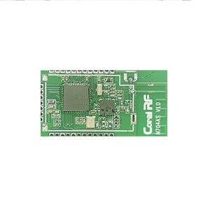
N704CS CC2674R10 ZigBee /BLE module based TI 2.4 GHz wireless mcu CC2674R10 and CC2592, the module designed for 2.4G band
Zigbee/BLE. It can be debug or program by customizer. The CC2674R10 module has +22 dBm output power and the sensitivity down to -102 dBm at 250 kbps(for ZigBee). The module support Zigbee 3.2 ,BLE 5.3 and thread and so on.
The CC2674R10 Module has a small encapsulation(35 x 18 x 3 mm), Integrated cc2674R10, CC2592 and pcb antenna, it reduced a lot of development troubles.
N704CS module hardware is designed for maximum range, 500m + Range (Low rate and Line of Sight).
cc2674R10 Features
Powerful 48MHz Arm Cortex-M33 processor with TrustZone
FPU and DSP extension
1024kB flash program memory
8kB of cache SRAM
256kB of ultra-low leakage SRAM with parity for high-reliability operation32kB of additional SRAM if parity is disabled
Dynamic multiprotocol manager (DMM) driver
Programmable radio includes support for 2- (G)FSK, 4-(G)FSK, MSK, Bluetooth® 5.3 Low Energy, IEEE 802.15.4 PHY, and MAC
Supports over-the-air update (OTA)
Ultra-low power sensor controller
Autonomous MCU with 4kB of SRAM
Sample, store, and process sensor data
Fast wake-up for low-power operation
Software defined peripherals; capacitive touch, flow meter, LCD
N704CS cc2674R10 Wireless protocols
N704CS cc2674R10 Module radio
N704CS cc2674R10 Module UART baud
N704CS Module Parameter
Model | N704CS |
| Frequency | 2400M --2500Mhz |
RF Data Rate | 1.2-4000 kbps |
Transmitting Power | +22 dBm |
Receiving Sensitivity | -102 dBm at 250 kbps |
TX Current | 160 mA |
RX Current | 9 mA |
Frequency Deviation | +/- 10 khz, tcxo optional |
Communication Distance | 10 – 500 m(Visual distance) |
Antenna Interface | IPEX, PCB antenna |
| Volume (mm) | 35 mm x 18 mm x 3 mm |
Operating Voltage | + 2V - 3.6 V |
Working Temperature and Humidity Environment | Temperature: -30 - 80 ℃; Humidity 10-95 %RH |
Storage Temperature and Humidity Environment | Temperature: -40 - 80 ℃; Humidity 10-95 %RH |
Weight (kg) | ≈10g |
N704CS Pinout Description
Pin Number | Function | Describe |
1 | VCC | + 2V - 3.6 V |
2 | GND | GND |
| 3 | DIO2 | MCU IO port |
4 | DIO3 | MCU IO port |
5 | DIO4 | MCU IO port |
6 | DIO5 | MCU IO port |
7 | DIO6 | MCU IO port |
8 | DIO8 | MCU IO port |
9 | DIO9 | MCU IO port |
10 | DIO10 | MCU IO port |
11 | DIO11 | MCU IO port |
12 | DIO12 | MCU IO port |
13 | DIO15 | MCU IO port |
14 | TMS | TMS |
15 | TCK | TCK |
16 | DIO16 | MCU IO port |
17 | DIO17 | MCU IO port |
18 | DIO18 | MCU IO port |
19 | DIO19 | MCU IO port |
20 | RST | RESET |
21 | DIO20 | MCU IO port |
22 | DIO21 | MCU IO port |
23 | DIO22 | MCU IO port |
24 | DIO23 | MCU IO port |
25 | DIO24 | MCU IO port |
26 | DIO25 | MCU IO port |
27 | DIO26 | MCU IO port |
28 | DIO27 | MCU IO port |
29 | DIO28 | MCU IO port |
30 | DIO29 | MCU IO port |
31 | DIO30 | MCU IO port |

1. Debug
STEP 1:
connnect N704CS module to XDS110 V3 by wire.
xds 110v3 | N704CS Module |
3V3 | VCC |
GND | GND |
| RST | RST |
TMS | TMS |
TCK | TCK |
STEP 2:
Used IAR or CCS 12 program it.
Note:
Please used the newest version.
2. RF test
step 1:
connect N704CS to XDS110
step 2:
1) Open smart RF studio 7,

2) Open cc2674R10 interface,

3) SET CC2592 IO
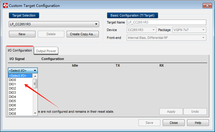
Then you can proceed with RF testing.
3. UART test
Download the uart2echo example fireware to cc2674R10 Module.
The table below indicates the serial port pins corresponding to GPIO.
UART | N704CS Module |
RXD | DIO2 |
| TXD | DIO3 |

4. GPIO test
Download the gpiointerrupt fireware to cc2674R10 module and run it:
Other example test please view the document.
File Download
CC2674R10 datasheet
N704CS datasheet